


IPC Clarifiers
| Model | Number of Plate Packs | Rated Capacity, GPM |
| IPC 30 | 1 | 30 |
| IPC 60 | 2 | 60 |
| IPC 90 | 3 | 90 |
| IPC 120 | 4 | 120 |
| IPC 180 | 6 | 180 |
| IPC 240 | 8 | 240 |
| IPC 300 | 10 | 300 |
| IPC 360 | 12 | 360 |
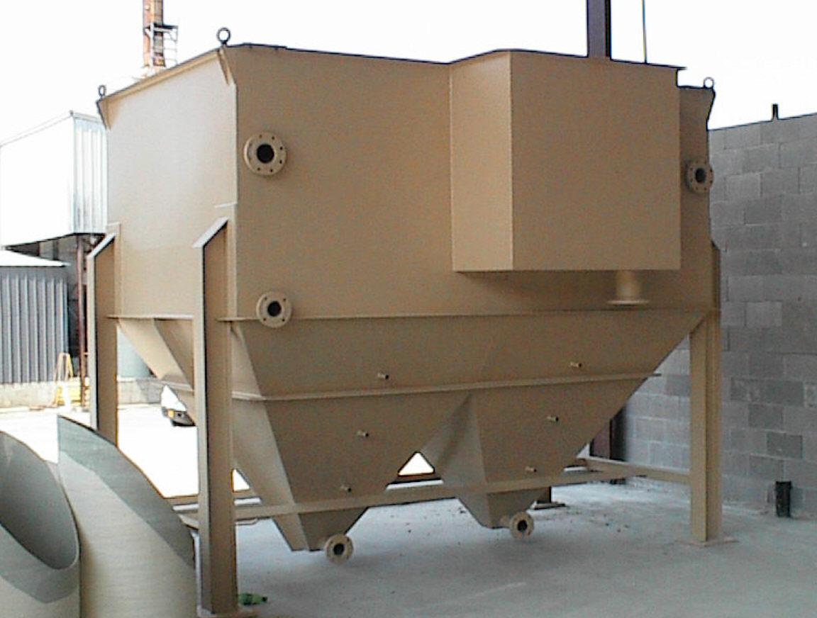 The Leaucon, Inc. IPC clarifier is designed to remove and thicken suspended and flocculated
solids from industrial waters and wastewaters in one step. The basic system consists of a plate
separator with a sludge collection cone underneath. A flash mix/flocculation tank usually precedes
the unit. The primary use of the IPC is to:
The Leaucon, Inc. IPC clarifier is designed to remove and thicken suspended and flocculated
solids from industrial waters and wastewaters in one step. The basic system consists of a plate
separator with a sludge collection cone underneath. A flash mix/flocculation tank usually precedes
the unit. The primary use of the IPC is to:
- Increase the efficiency of the sedimentation basin resulting in a reduction of required basin area by a factor of 80%.
- Produce a highly dense underflow of high concentration, which leads to an appreciable reduction in dewatering costs.
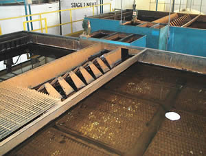
Before we go further into a discussion of the unit, it would be beneficial to cover the principle of the IPC plate separator. This device, which couples the benefits of flat plate settlers and tube settlers, is designed to increase the settling capability of a basin. The design principle utilizes the fact that the depth of a gravity settler has very little bearing on its' settling capacity. Of much more importance is the available settling area of more than 180 sq. ft. in each IPC plate pack.
In a conventional clarifier or sedimentation basin, the available setting area is limited to the area of the bottom. The IPC principle utilizes a series of inclined honeycomb plates mounted together in a pack. There is only a short distance in the honeycomb openings of two inches in the IPC design. With this principle, the available settling area becomes the total area of the plates projected on a horizontal surface.
It should be remembered that in a conventional settling basin, the sludge particle often has a considerable distance to traverse before reaching the bottom. In an IPC, this settling distance is something less than two inches.
Since the IPC plates are mounted at a 60-degree angle to the horizontal, the settled sludge can easily slide down the plates for collection.
With the IPC, the wastewater entering the unit is introduced slightly below the IPC plate separator, allowing the majority of the solids to be discharged over and settle out over essentially the entire surface of the sludge collection basin, the lower part of which is designed as a hydraulically static thickener. This design allows for 100% use of the approximately 180 sq. ft. of settling area in the pack to be utilized for separation of a reduced solids concentration up flow. With the efficiency of horizontal plate separators being fixed for each type of wastewaters and solids particles, the net effect of the design is lower supernatant suspended solids concentrations.
Contrary to conventional inclined plate clarifiers, where a continuous flow of sludge of up to 10% of the rated capacity of the unit is rejected from the cones, the IPC produces an underflow 4 to 6 times denser in most applications.
This is due to the conservative cone volume designed into the unit, and the timed rejection of sludges. In standard applications, dense sludge is hydrostatically pumped during an 8-12 second period every 30 to 60 minutes. This allows for removal of only the highly dense sludge at the cone's bottom.
During the timers off period, the solids collecting in the cone are subjected to the extended period of static thickening.
The IPC method of removing only the densest sludge through the full three-inch pipe, eliminates the requirement for supplemental expensive thickener equipment, and prevents "rat holing" in the sludge bed.
For each application, the timed sludge withdrawal is field set. Sampling ports provided on the IPC's cones allows for a convenient method for determining proper settling.
The standard IPC clarifier consists of a flash mix/flocculation chamber, the specially designed honeycomb plate pack and the coned thickener underneath.
Water enters the first chamber of the flash mix/flocculation chamber. For many applications, polymer addition is necessary to increase particle size. Where required, polymer is applied into the first chamber; a mixer provides the rapid mixing necessary for uniform application and dispersion. The waters then are transferred through a series of overflow/underflow baffles, where the gentle mixing accomplishes floc growth. Retention time required with this IPC design is 1 to 2 minutes. In contrast, competitive units require 10 to 20 minutes of flocculation times in significantly larger and more costly tanks.
The flocculated wastes enter the IPC unit in an influent launderer and flow distributor. Uniform distribution of flow accomplished by the launderers allows for even distribution of solids onto the sludge bed and hydraulic loadings upward through the plate pack.
The clarified water rises up the plates and is discharged near the top over weirs into effluent troughs mounted above the plate packs.
The settled sludge slides down the plate into the thickening compartment below the plate pack and is applied to the surface of the sludge bed.
The dense sludge collected in the cones is removed on a timed basis for additional dewatering. Sludge removal is made by a timer actuated solenoid valve controlling a diaphragm valve on the cone. As air pressure is applied to the diaphragm valve, the valve opens allowing the dense sludge to be driven by the hydrostatic head pressure of the unit, through a three-inch sludge-piping network into a storage tank.
The main advantages of the IPC clarifier over competitive inclined plate settlers are:
- Conservative sizing provides for plate pack hydraulic loading rates of 0.2 GPM per sq. ft.
- The unique honeycomb plate pack couples the effective surface settling area of flat parallel plates with the reduction in cross flow turbulence benefit of tube settlers.
- Standard equipment includes flash mix/flocculation, flash mixer, epoxy lining, pilot solenoid valve, butterfly valve, and diaphragm valve.
- Cone volume and static thickening, coupled with timed sludge blow down eliminates the need for further thickening.
- Maximum unit height of 12 feet allows for installation in most any plant without building modifications.
- Use of a launderer system for flow distribution rather than submerged orifices, insures uniform flow because of possible plugging of orifices.
- Our design allows for cleaning of plates without removing the effluent troughs.
- The IPC design allows for visual assurance of uniform flow at the effluent launderer and adjustable troughs.
Other features of the IPC over conventional clarifier systems are:
- Surface area of sedimentation basin reduced up to 80% against conventional and up to 50% versus tube settler systems.
- Ability to produce dense easily dewatered sludge underflows, typically four to six times conventional sedimentation or tube settler systems.
- Up to 50% reduction in cost of sedimentation basins.
- Performance relatively unaffected by changes in the solids loading.
- Immediate start-up of system under full load.
- Effluent quality unaffected by hydraulic shock loads.
Applications
Typical applications of the IPC Clarifier include the following:
- Water Treatment
- Potable Water
- Process Water
- Makeup water for cooling towers
- Water for manufacturing products
- Pretreatment boiler feed water
- Designed to treat non-biological or minimally biologically active wastewaters for removal of suspended solids.
- Metal Finishing and electro-plating wastewaters for removal of metal hydroxides.
- Power plant wastewaters for removal of fly ash, metal hydroxides, etc. These would include wastes from scrubber systems, coal pile runoff, air preheated wash waters, fireside wash waters, boiler blow down, etc...
- Removal of and thickening of suspended solids (refuse) from coal plant wash waters.
- Treatment of scrubbing waters for calcium sulfate removal.
- Treatment of paper mill effluent water for color removal with alum.
Sizing and Design
Loading rates normally used in the design of conventional clarifiers can usually be applied directly to the sizing of IPC units by substituting projected settling area for the surface settling area of the conventional unit.
Each of the specially deigned IPC inclined plate packs are constructed of PVC sheets formed to create a honeycomb design. The honeycomb plates are supported in a coated carbon steel shell. Each plate pack is inclined at an angle of 60o measured from the horizontal, and has an effective settling area of more than 180 sq. ft.
Conventional and competitive clarifiers generally size units for hydraulic loading approaching 0.5 GPM per sq. ft. of settling area. With the IPC conservative hydraulic load rating of 0.2 GPM per sq. ft., each plate pack is rated for efficient solids removal at 30 GPM.
Suspended solids loading concentrations applied to the unit will vary with the type and settling rates of material to be removed. Bench scale testing for each application is recommended. As a rule of thumb, the IPC plate pack will separate all solids that settle one inch in five minute in a liter beaker and at rated flows. Tests can be made in bench scale testing or at the flocculation tank for on-site testing.
In the case of metal hydroxides, units have shown to operate effectively at solids loading of 1000 ppm at rated flows of the units, for a solids removal rate of 15 lbs. per plate pack per hour for optimum efficiency.
Difficult settling solids applications can often be improved with proper pretreatment or coagulation using iron or aluminum salts. The proper testing and selection a polyelectrolyte often proves critical.
Reactive or gas forming wastewaters generally require that gases be exhausted from the waters prior to delivery to the IPC. Minute gas bubbles affixing to floc solids can render the floatable. Rapid increase in water temperature is often times the source of gas liberation. The IPC, like any other sedimentation device, will not separate non-settling particles.
Standard IPC models vary from the Model 30, containing one plate pack and a 30 GPM rating, to the Model 360 containing 12 plates packs with a 360 GPM rating. Increased capacity requirements are attained by series and parallel operation of the modules.
Standard Model Include
| Model | Number of Plate Packs | Rated Capacity, GPM |
| IPC 30 | 1 | 30 |
| IPC 60 | 2 | 60 |
| IPC 90 | 3 | 90 |
| IPC 120 | 4 | 120 |
| IPC 180 | 6 | 180 |
| IPC 240 | 8 | 240 |
| IPC 300 | 10 | 300 |
| IPC 360 | 12 | 360 |
Units are constructed of rugged 1/4" rolled carbon steel, with joints welded inside and out. All wetted parts are sand blasted to near white (SSPC SP-10) metal, then coated with an epoxy paint to resist corrosion. Exterior surfaces are, likewise sand blasted to a commercial finish (SSPC SP-6) and coated with epoxy paint. (Full paint specifications are available for review.) Influent self cleaning V-notch weirs and effluent launderers are similarly epoxy coated and provide even flow throughout the plate settling area. Rugged 150# flanges are provided at the inlet and all outlets.
Included as standard to the IPC units is the built in flash mix/flocculation section with a high-speed mixer and air operated blow down valve(s). The conservative sludge collection and static thickening cone sizing eliminates the need for additional thickening devices prior to dewatering.
Liquid retention times average 25-30 minutes at rated flows in the IPC units, compared with 12-15 minutes in competitive models.
Maximum height of the IPC units is 12 feet in the Model 360. The relatively low heights are often advantageous in areas where ceiling height restrictions often become a problem.
The IPC design offers simplified pack cleaning with the installation of our pack-cleaning valve. The valve, when opened, allows draining of the unit to below the plate packs. Simple hose down of the pack quickly removes floc build-up sometimes caused by polymer overdose. The pack-cleaning valve eliminates the need for high-pressure air or manual rodding of the plates, which could cause breakage. Should serious plate pack blinding ever occur, both the effluent launderer and packs are removable.
The timed blown down of the dense sludges from the IPC cone via the automatic opening of the diaphragm valve, both improves solids concentration of the wasted sludges and eliminates "rat holing". It is recommended that sludges be transferred to a sludge holding tank using the hydrostatic head pressure of the clarifier. Inlet height to the sludge holding tank should be a minimum of two feet lower that the clarifier surface for efficient transfer.
The timer settings for frequency and duration of blow down are field set for each application.
Three 3/4" sludge sampling ports are provided on the IPC cone to determine height of the sludge blanket and to assist in proper settings.